What is GFCI Protection, and Why Do I Need It?
The Complete Guide to Ground Faults and Ground-Fault Protection
Introduction
Of all the electrical hazards in our lives, ground faults are probably the most common but least understood. One out of every four American consumers do not know the purpose of their ground fault circuit interrupting devices (GFCI’s), nor that they can prevent electrical shock and electrocution[i]. This is a deep subject and can be technical, but its importance to safety cannot be overstated. The Consumer Product Safety Commission (CPSC) estimates 50 percent of home electrocutions have been prevented since the introduction of the GFCI,[ii] a device that automatically detects ground faults and breaks a faulted circuit. Before GFCI’s, nearly 800 people died each year from electrocutions in the home. But now, the household electrocution death rate is down to less than 200 a year.[iii]
We believe those numbers could drop even more with proper education. That is why we are taking the dangers of ground faults seriously and spreading the word about preventive measures and best practices. This article will help you understand, not only what electrical ground faults are, but what you can do to protect yourself and loved ones with ground fault circuit interrupting devices.
What is a Ground Fault?
The most common definition is “an unintentional electrical path between a power source and a grounded surface.”[iv] This seems easy enough to understand but is actually more technical than the average person realizes. For instance, what is a grounded surface? And we understand “unintentional” but would an intentional path ever be okay? (The short answer is, yes!)
Let’s break it down.
Anything “grounded” simply means it is connected electrically to the earth. A grounded surface, then, is an extension of the earth’s electrical potential. As such, any grounded surface should have the same electrical charge as the earth it is connected to. There should be no voltage between the two. Of course, nothing is ever quite perfect in the real world. Because of varying resistances and distances along a conductive path there may be a few millivolts up to several volts of difference between one of its locations and another. In most cases, the difference is too small to matter. Essentially, in the same way one end of a copper wire is electrically the same as its other end, something that is grounded should be one with the earth, electrically.
We said a ground fault is a “path,” which means electricity can travel on it. As in life, there are easy paths that are smooth, wide, and straight, and there are difficult paths that have obstructions; they are narrow and crowded, crooked, choked. You name it. Electricity may travel many paths, but not all paths are equal. Some paths “impede” or resist current flow more than others. And, just as gravity affects every path we walk on, all electrical paths resist current flow to some degree or another.
The term “ground fault” can be misleading. A ground fault may have little to do with the earth. Instead, its unintentional path may travel mainly through the system of bonding jumpers and grounding conductors back to the source, with only a small amount leaking through the ground. Because our electrical systems are grounded, these bonding paths are grounded surfaces.
Electricity will take all available paths to return to its source. You may have heard, “electricity just wants to go to ground,” or “electricity always takes the path of least resistance,” but neither statement is accurate. If there are a million paths, the current will be shared on all million at the same time. The amount of current an individual path contributes will depend on its own resistance, the total resistance (impedance) of all available paths, and the amount of voltage pushing the current through them.
Normal Current Flow is Intentional.
In trying to get a clear picture of what a ground fault is, it may be helpful to first understand how a normal electrical current path functions. Electrical current, measured in amperes (Amps), is the flow of electrons through a conductor. For electricity to do our bidding safely, we design “circuits” as the designated paths for currents to follow.
An Intentional Circuit:
- begins at a specific electrical voltage source (a battery, a generator, or a transformer).
- is protected close to its source by a breaker or fuse.
- passes through a “load” (electrical utilization equipment such as a toaster or a desktop computer) in order to do a specific job.
- Follows a planned route to return to its source. Electricity does not want to “go to ground,” but if it wants anything, it is to return to its source.
An important thing to keep in mind when discussing electrical safety and current flow is that, aside from static electric phenomena such as lightning strikes, for current to flow there must be a round-trip, complete path, to and from a source. If there is any break in the path, and if no other path is available, the flow of current will stop instantly.
We further ensure electrical safety and proper usage of electricity by using insulated conductors, and we take care to prevent electrical collisions (aka “short circuits”) by keeping all the different paths isolated from one another at connection points. If things proceed according to design, all is well. But in the case of a ground fault, electricity escapes its designated path and takes other paths back to its source. This may be only a small part of the electrical current veering from the path intended. To be a ground fault, it does not even need to be all of the current going astray, it is still potentially lethal.
What Does a Ground Fault Look Like?
We know how a proper circuit is supposed to behave; we know the safety measures of design to keep all intended paths separate and directed through a load and back to the source. But to understand the dangers of a ground fault, the next thing to realize is that the possibilities are endless. A ground fault can take any one unintended path, or it can spread out and take many.
A couple of key concepts to understanding how electrical current flows on a path are “resistance” and “impedance,” which sound like the same thing because they are related, but have an important difference. To explain, if voltage is the pressure pushing electrons through a conductor, then resistance is the property of that conductor which restricts the flow. Impedance is one level higher and describes the total resistance of all the different component resistances of an entire path; it is the total resistance to be overcome for current to flow in a circuit. Resistance will make one path easy and another path difficult, and in the case of parallel paths where multiple paths all share the current, resistance will also determine how much current each path will receive. Impedance will determine how much current flows through the entire path.
Bringing it back to safety, there are three main categories of hazards for a ground fault path to take: The Low-Impedance path, the dangerous High-Impedance path, and the very dangerous Open-Ended Hazard.
The Low-Impedance Path:
The first category of a ground fault scenario is our ideal, the Low-Impedance, or Bonded-Grounded path. It’s the next best thing apart from everything going right. When we intentionally bond all nearby non-current carrying metal parts together in a complete path back to the source, this becomes the emergency, back-door escape route that we want current to take, should something go wrong.
In any ground fault scenario, an unintentional path is created between a point in the circuit meant to carry current and its source. This could be a wire that has come loose from an intended connection point, such as from a terminal screw or wire nut. The hot conductor then contacts the metal casing of an enclosure such as an electrical box. It could be a section of a circuit that is damaged by a nail or rubbed raw by a vibrating metal duct. But, if all these parts are electrically bonded, our stray current can beat a hasty retreat back to its source, and Boom—a fuse blows or breaker trips, because it was a low impedance path and the rush of current was too high for the protective device to carry. This is good because the current stops instantly. Lives and property are saved. Such is the case of a properly-protected low-impedance path ground fault.
The High-Impedance Path:
While grounding an electrical system makes our electrical safety more consistent, it can also make the very earth beneath our feet more dangerous. The high-impedance ground fault uses a path that is too restricted to allow a high current through it. Generally, it will follow paths through the earth and other grounded surfaces that are not ideal conductors to reach the source. And with high impedance, we get low current. This means that a fuse or breaker may not be able to open the fault and save lives. So, if the fault is allowed to continue this way, a person could unwittingly step into connection points along the path and become another parallel path in the fault. This can be fatal and has claimed many unsuspecting victims because, when you are being shocked, you may not be able to get away from the electricity flowing through you.
The Open-Ended Hazard:
At this point in the scenario, there is a third hazard that exists as a subset of the other two. We have described what happens if there is a completed path from a voltage point back to the source. Whether it is a High-Impedance or Low-Impedance path, current will flow through it back to the source. The hazard of the Open-ended fault is that there is not a complete path...yet.
For example, sometimes a section of metal water pipe (which should be bonded to earth) needs to be replaced, but today plastic piping is often used as a replacement instead. This is fine as long as a bonding jumper is fastened in place on both ends to ensure the continuity between both parts of the metal piping system. If, for some reason the metal parts are not re-bonded with a jumper, or the bonding connection comes loose, there is no longer a complete path, and part of the piping system has just become an island, disconnected from the earth. If damage then occurs to a hot conductor and it makes contact with the orphaned section of metal piping nearby, electrical potential will simply extend out to the furthest part of the new conductor(s) and wait for a complete path to be made back to the source.
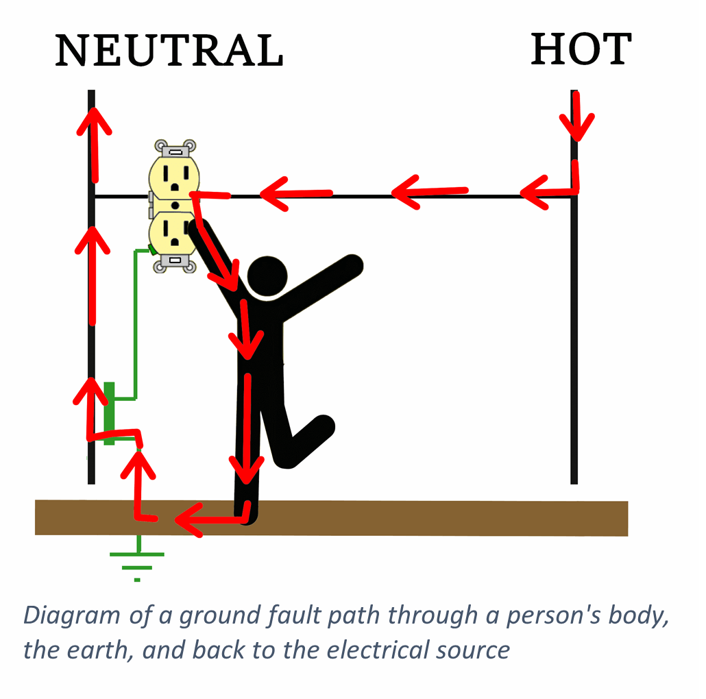
That opportunity could come along in the form of a person, unknowingly brushing up against an electrified surface while standing on the earth or some other grounded surface. At this point, a complete path would then be created, and the person would become the major link with current flowing through him or her to the ground and back to the source. This is a serious shock hazard that has killed many people. But ground fault dangers can be greatly mitigated with GFCI devices.
Why does electricity use the earth as a path?
Residential electrical systems, at least in the United States and Canada, are grounded in your service transformer (at the “neutral” or middle point in the secondary winding, to be exact). This is done by the utility company, and it is what makes your electrical system “grounded.” It simply means they have referenced the entire system to a common voltage point, the earth. Another way of looking at it is that the earth has been made to have the same electrical potential or voltage as the center point of the voltage source. The earth and the neutral point become unified, electrically.
With grounded systems, we are required to maintain (that is, to extend) the earth’s electrical potential in specific places. We drive ground rods at our Main Disconnects and bond all the non-current carrying metals in our systems to the earth there. This is also the only place where our neutrals and grounding conductors all get bonded together which keeps current from flowing on the grounding system in normal situations. What this does, in effect, is to make the surface you stand on roughly the same in potential as the neutral conductor in all your receptacles.
Because the earth is an extension of the neutral, it can become a ground-fault path. However, the National Electrical Code (NEC) states that the earth must not be considered an effective fault current path. This is because the earth’s resistance varies greatly depending on composition and conditions.
If current is impeded (restricted) enough, it will still flow but will be diminished to the point that, although still deadly, it may never rise to the level of tripping a breaker or blowing a fuse. And if part of the fault path travels through a person’s body they may be electrocuted. The fuse would never blow or breaker never trip, and the fault would continue until someone else finally turned off the circuit.
What is a GFCI?
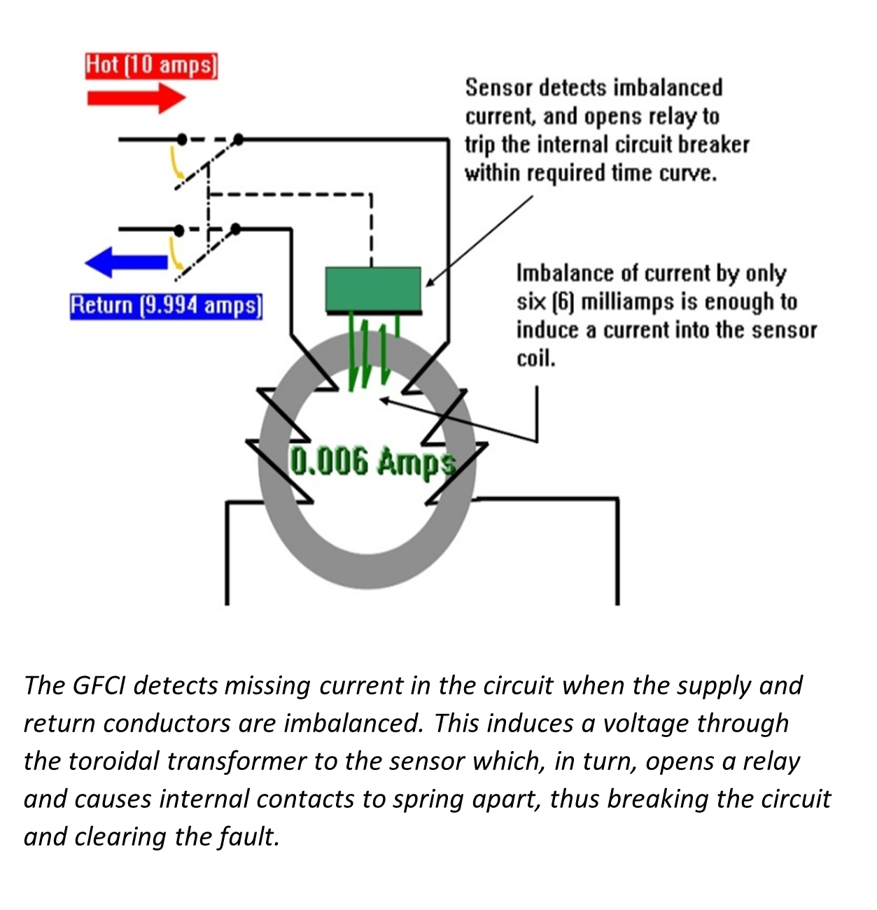
A Ground fault circuit interrupting device (GFCI) protects us from shocks by breaking a circuit when an imbalance of current flow over time is detected. An “imbalance” means there is a different amount of current coming in on the circuit than there is going back, which would indicate a ground fault or electricity taking some other path than the one intended. GFCIs are sensitive enough to detect and open faulty circuits with imbalances of only 5 to 6 milliamps.
GFCI’s are required by UL standards to break circuits on a trip curve. That is, they open based on the intensity of current over time. This allows a smaller and less dangerous current leakage to last longer than a greater one, and reduces nuisance tripping while still providing adequate shock protection. For example, with a 6-milliamp current leakage, the GFCI has up to 6 seconds to break the ground fault, but with ground faults of 30 milliamps it would open in under 20 milliseconds – quick enough to keep most human hearts from going into ventricular fibrillation. Once the faulted circuit is broken, current stops flowing.
How does GFCI protection work?
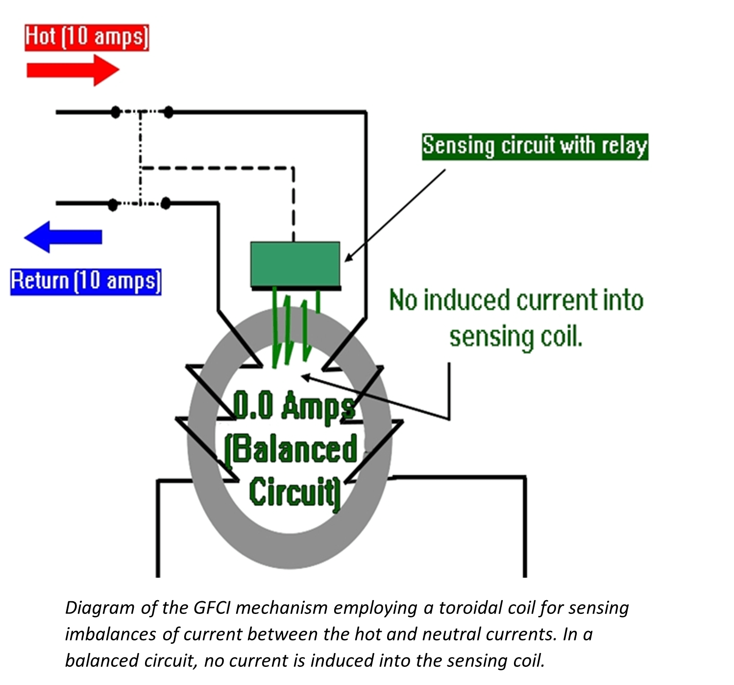
GFCI’s use an ingeniously simple mechanism for detecting stray currents. They utilize a doughnut-shaped iron ring inductor called a toroidal coil to help contain magnetic fields.
Both the hot (supply) and neutral (return) legs of the circuit are coiled around the sides of the ring. Along with these, a secondary coil is used for a sensor that would naturally pick up induction through any magnetic fields created by current in the live circuit.
With this set-up, as long as the hot and neutral currents are equal, their magnetic fields cancel one another, and no current is induced into the sensor coil. If they become imbalanced, which would indicate a ground fault, a current is induced into the sensor which in turn activates a relay to open internal contacts in the receptacle, thus breaking the circuit and stopping current flow.
Can I still be shocked, even with a GFCI?
Yes, because GFCI’s only detect an imbalance in the circuit. If you complete a circuit by touching both the live hot and neutral components of a GFCI device, while being insulated from ground, a balanced current will flow through you. The GFCI will not trip. Also, if you touch the hot terminal screw on the line side of a GFCI, it will not trip. GFCI’s only monitor the currents flowing through their toroidal coil.
Where do I need a GFCI?
The National Electrical Code calls out many specific requirements for GFCI protection. The following requirements are a summary of the locations most common in a home setting.
Note: These requirements are taken from the NEC 2020 code cycle. Check with your local codes as they may differ significantly both in code cycle and addendums.
- Ungrounded Receptacles – If you want to use a three-prong receptacle at a location where there is no equipment ground, the NEC does allow it if GFCI protection is used, and the receptacle is clearly and permanently labeled as having “no equipment ground.”
- NEC 2020 Requirements for newly constructed Dwelling Units (all homes, apartments, etc. where people dwell):
- Note: When measuring the distance from receptacles, it is the shortest path the supply cord of an appliance connected to the receptacle would follow without piercing a floor, wall, ceiling, or fixed barrier, or the shortest path without passing through a window.
- All 125-volt through 250-volt receptacles in the following locations must have GFCI protection for personnel.
- Bathrooms – all receptacles in dwelling unit bathrooms.
- Garages and outbuildings – If it has a floor at or below grade level, and it is only used for storage, or as a work area or similar types of areas, it must be GFCI protected.
- Outdoors – Any receptacle installed outdoors requires GFCI protection, unless it is a branch circuit dedicated to snow melting, deicing, or pipeline and vessel heating. But to qualify for the exception, even these must have GFPE (ground fault protection for equipment) of 6 to 50 milliamps to protect the equipment.
- Crawl spaces – If the receptacle is in a space where the “floor” is at or below grade level, protect it with a GFCI.
- Basements – In previous code cycles, this rule used to only require GFCI protection in unfinished areas of basements, but as of the 2020 NEC any 125- through 250-volt, single-phase receptacle in a basement needs GFCI protection. The ONLY exception allowed is for fire or burglar alarm system receptacles.
- Kitchens – where serving the countertops.
- Sinks – if the receptacle measures 6 feet from the inside edge of the bowl. This means, if the garbage disposal, trash compactor, dishwasher receptacles are located under the sink and a six-foot cord could plug in and reach to the inside edge of the sink, it must be GFCI protected. If the refrigerator receptacle is within that boundary, it also must be GFCI protected. But now, with the additional requirements for the 250V receptacles, even Electric Ranges or cooking appliances with their receptacles within the six foot must be GFCI protected.
- Boathouses – all receptacles.
- Bathtubs or shower stalls – within 6 feet of the outside edges. This rule is similar to the sink rule, but notice it is measured from the outside edge, not the inside.
- Laundry areas – all receptacles located in an area where laundering is done, whether 125V (110) or 250V. This means not only the washing machine receptacle and other utility receptacles in the area, but also the dryer.
- Sump Pumps [422.5(A)(6)] – all sump pumps, no matter where they are located must have Class A GFCI protection. Class A GFCI devices are required to trip at current imbalances between 4 and 5 milliamperes.
- Dishwashers [422.5(A)(7)] – The 6-foot sink rule would normally cover this, because most dishwasher receptacles are located beneath the sink, often on the same circuit as the garbage disposal. With this rule, it no longer matters where the receptacle is located. All dishwashers with 150V or less to ground and 60A or less must be protected with a Class A GFCI device.
- There are also GFCI requirements specific for situations regarding permanently installed swimming pools, hot tubs and spas. It is best to use an electrician especially knowledgeable for electrical installations in these areas.
- Anywhere you want to feel safer. The general rule is if it is anywhere near water or in a damp location, it is a good idea to have GFCI protection, whether it is specifically required or not.
What options are available for GFCI’s?
You can get GFCI’s as receptacles and breakers. There are also portable versions such as manufactured GFCI assemblies on extension cords and special plug assemblies on the utility cords of certain appliances and equipment.
In receptacle form, there are optional features to consider; some of them are required. Here’s a list of significant options for GFCI receptacles in and around the home:
1. Tamper Resistance – Most receptacles in the home are now required to resist attempts to get at their slotted entries with anything other than a two- or three-pronged plug. The design uses a blocking mechanism that prevents entry at single slots. This keeps children from pushing objects (keys, nail files, screw drivers, etc.) into one slot or the other of the receptacle.
2. Pilot Light – a highly visible LED light indicates the receptacle has power in most lighting conditions. These are popular in commercial kitchens where all receptacles must be GFCI protected. However, they are useful as well in dark corners of basements and other dimly lit areas where a strong visual cue from a distance would be convenient.
3. Self-Testing – As we discuss below, testing GFCI’s should be done at least monthly. The self-testing feature will do the task for you continually. Its green LED light turns red when something is wrong. This is a widely available feature; just look for the words “Self-testing” on the packaging.
4. Weather-Resistance – If you are installing an outdoor receptacle that needs GFCI protection, make sure to use a weather-resistant GFCI. They are required along with “in-use” covers that provide physical protection from inclement weather, even when a cord is plugged into them.
5. Audible warning– In specific locations such as for basement sump pumps and freezers, this is a great option to look for in your GFCI. It will sound an audible alarm when it has tripped.
Note: While an audible alarm might suffice if you are at home, we found at least one company with an app and smart plug adapter solution. It sends notifications to your cell phone or email should the power go out on a circuit. As smart technology and products develop, we expect built-in network connectivity in the near future as an option for smart GFCI receptacles and breakers. Disclaimer: We have neither tested, nor are affiliated with the GFI Notify brand and receive no benefit for listing it as a possible solution.
Testing your GFCI’s is just as important as installing them.
As with any lifesaving equipment, regular testing is necessary. And it makes sense, after going to all the trouble of installing ground fault protective devices. Checking them frequently to make sure they are still capable of performing their function guards the investment.
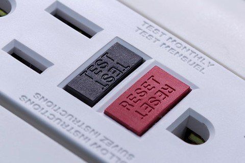
Read the manufacturer’s instructions and you will find a regimen for pressing the test button, usually once a month. The test simulates a ground fault by cutting a resistor into half of the circuit. A receptacle in good working condition should trip off. To reset the device, press the reset button in far enough until a click is heard. This might require a little more pressure and depth than you would expect. A screwdriver usually works better than a fingernail.
Summary:
· For current to flow in a circuit there must be a round-trip, complete path, to and from a source.
· If there is any break in an electrical path, and if no other path is available, the flow of current stops instantly.
· A ground fault is an unintentional electrical path between a power source and one of its remote voltage points, usually through grounded surfaces.
· A grounded surface is an extension of the earth’s electrical potential.
· Normal current flow is intentional; it follows a planned route to return to its source.
· GFCIs save lives; since their introduction, electrical deaths have been reduced by at least 75% and home electrocutions have been cut in half.
· GFCI protection is required for many outlets in dwellings.
· GFCI’s, along with all lifesaving equipment, should be tested at least once a month.
[i] https://www.nickleelectrical.com/safety/electrical-safety-statistics
[ii]50 percent of home electrocutions have been prevented since GFCI’s
[iii] nearly 800 people died each year from electrocutions in the home. Now, it is less than 200 annual deaths.
[iv] https://www.cpsc.gov/s3fs-public/099_0.pdf