Call  620-931-0614

Why is One Slot Longer Than the Other in My Electrical Outlet?

David Sanders • Mar 17, 2022

Q: Why is one slot longer than the other in my electrical outlet?

A: At first glance, this question makes me chuckle. “This’ll be easy,” I think. It strikes me as childlike, a “Why is the sky blue?” sort. You know the kind of question: simple on the surface, barely warranting a second glance. But when you try to dispatch it, it doesn’t budge. And dive a bit deeper, there’s an iceberg-sized topic, with massive safety implications, waiting below.


The short answer to the question is, we are talking about the polarized receptacle and its counterpart, the polarized plug, which has one wide blade and one narrower blade. The different blade widths ensure they’ll fit together only one way.


Of course, it’s a safety design. But why does it have to make life so difficult?


If you’ve ever struggled to plug something into a receptacle outlet only to find you’ve been holding the plug upside down, you are not alone. So maybe the better question is, why do we need the polarized plug and receptacle? Read on to learn more.


Uneven Slots are the Hallmark of a “Polarized” Receptacle


In General, receptacles and attachment plugs provide both a safe and convenient way to temporarily connect appliances into your electrical system. Removal is equally safe and convenient. Let’s discuss how the receptacle and plug connection has been a good idea from the beginning, and how the design has improved over the years to give us things like the polarized receptacle.


Consider an appliance such as a vacuum cleaner, designed for use with 110-Volts. It has a cord and plug for attachment to the electrical system, but the vacuum can’t be energized accidentally. It must first be plugged into a receptacle matching its plug. And, after using the vacuum cleaner, you can safely switch it off and disconnect it from the circuit by simply pulling the plug out of the receptacle. It can be stored in a closet with no fear of it causing an electrical fire. No power, no danger.


To add to the convenience, the appliance can be moved about from one location to another and plugged into an identical receptacle across the room. Off you go again, cleaning house. Meanwhile, back at all the receptacles, the live parts of the circuit are always safely recessed in non-conductive thermoplastic.


Sometimes, the things we take for granted can hurt us.


Imagine a housewife in 1946. She’s excited, because even though her house was built in 1926, she is the proud new owner of her very own electric vacuum sweeper. And she is the first on her block to have one.


One day she plugs in her vacuum and starts cleaning rugs. But the beater bar stops turning for some reason. Suspecting a broken belt, and being a mechanically inclined woman, she switches the machine off at the handle, kneels, and begins taking it apart to see what is wrong.


When she casually touches an exposed electrical connection, a sudden wrenching shock surprises her. It runs up her arm, down through her heart, and out her knee to the floor. Luckily, she manages to drop the sweeper and is not seriously injured.


But what happened? The machine was turned off, so how did it deliver that shock?


The answer turns out to be that her vacuum did not have a polarized attachment plug. In other words, one prong was not wider than the other. The plug could be inserted into a receptacle either right-side up, or upside down. In this case, it was plugged in upside down and the correct polarity was reversed.


When she turned off the machine at the switch and did not pull the plug, all the electrical parts of the machine stayed energized inside, except for the point beyond the switch where it was broken from continuing back into the receptacle’s neutral return slot. In other words, the return path was broken at the switch instead of the hot lead as it should have been!


The History of Polarity


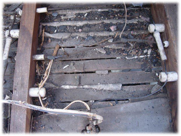
Years ago, receptacle devices were made with two identical sized slots. In the United States, you can still find some pre-1930s vintage homes with these non-polarized, two-slotted receptacles. The symmetrical slots meant a lamp or other equipment could be plugged in haphazardly, with either prong becoming the hot path to the equipment.


Because household electrical current constantly changes direction, most equipment will run with the plug inserted either way. But as for safety, if the equipment has a manual built-in single pole switch or contains an Edison-style screw-shell for a light bulb, reversed polarity can create dangerous problems.


As with our cautionary housewife, any user, thinking that a switch in “off” position and an appliance not running means the appliance is safe, might be in for a shocking surprise. As a general rule, always cut the power before working on electrical wiring.


Over the years, there has been a steady progression of design improvements made for our electrical safety.


The polarized receptacle was one of the earliest improvements, created way back in the 1880s in Britain. One of its holes or slots was larger than the other, and this small improvement meant no more reversed polarity accidents. Sadly, the design was not put into wide-spread use in the United States until the 1930s.


It was even later, apparently in 1962, that the US National Electrical Code began requiring all receptacles to be both polarized and grounded. Finally, in 1969, Underwriters Laboratories mandated all new appliances manufactured with switches and/or screw shell light sockets had to be equipped with polarized plugs.


Today, the National Electrical code requires any cord and plug equipment to have either a polarized or three-pronged grounding-type plug, if it has any one or more of the following features: a manually operated single pole switch wired into the hot lead, an Edison-style screw shell for a lightbulb, or a built-in 15- or 20-amp receptacle.


Advances in electrical safety have led to further improvements in receptacles beyond the polarity design, but none have yet superseded its necessity.


Today, new design elements have been added to work together with the polarized receptacle and are already becoming widespread. One of these is the tamper-proof receptacle, which has a mechanism to prevent objects other than attachment plugs, such as screwdrivers or butter knives, from being inserted into one of its slots. This feature helps keep children safe in the home.


While all new homes are required to be fitted with tamper-proof receptacles, it is never too late to add them to your existing home. If you are updating, ask your electrician about installing them to replace your regular three-pronged grounded receptacles.


One more advance for safety that should be mentioned is ground fault circuit interruption. New electrical installations require protection by either GFCI receptacles or GFCI breakers in many areas in and around the home, but existing homes often need to be updated with this extremely useful device, as well.


One special benefit of GFCI technology: it is the only code-approved way for putting a three-pronged receptacle on an existing two-wire, non-grounded circuit.


NOTE: Any GFCI receptacle or GFCI-protected three-pronged receptacle without a connection to ground should be clearly marked with “No Equipment Ground” and “GFCI Protected.”


In Summary:


  • Polarized receptacles and plugs are an important safety design for ensuring proper cord and plug connections.
  • The main benefit of the polarized receptacle and matching plug is to ensure a hot to hot and neutral to neutral connection in equipment plugged into it.
  • A non-polarized attachment plug may be a hazard. Your electrician can replace it with a safer polarized plug.
  • Your electrician can replace your non-polarized wall receptacles with safer polarized versions.
  • Both tamper-proofing and GFCI technology is available in polarized receptacle form. These advances further ensure your electrical safety when properly installed and functioning correctly.
  • Test GFCI and all life-safety devices at least once a month.


Terminology


Receptacle – A connection device for allowing cord-and-plug equipment to be temporarily connected into the electrical system. Receptacles have slots and are the female part of the attachment pair.


Outlet – An accessible point in the electrical system where current can travel to-and-from to supply utilization equipment (such as a lamp, fan, or corded drill, etc.). Notice, an outlet is technically not the same thing as a receptacle, though the terms are often interchanged. Don’t worry. Your electrician should understand what you mean if you forget and say, “outlet,” when you really meant, “receptacle.”


Polarized – For our purposes, “polarized” means there are two differing sides designed to fit only one way in a connection. Using the term “Polarity” can be slightly confusing in describing electrical attachments, because there’s another use of the term. When speaking of household electricity, in the United States and some other countries, current “alternates” at 60Hz. This means the electrical polarity reverses direction 120 times per second. 


* NOTE: If for some reason your receptacles were wired with “reversed polarity,” it really is a safety concern, and your electrician can detect and fix the issues. *


Plug – In the same way an ordinary plug is something inserted to stop a hole, the electrical “attachment plug” has prongs designed to fit into the slots of a receptacle. For this discussion, a “plug” is the male end of an electrical cord. You may have seen older equipment that did not have a polarized plug. Although it will still work in a polarized receptacle, your electrician can replace the plug end with a safer, polarized one. You may also choose to replace the entire cord with a new appliance cord.


Grounded – Connected to the earth or “ground.” Although the concept is simple, this term really deserves an article all its own. Modern house wiring now includes an extra wire attached at one end to a point in a distribution panel that is connected both to the earth and to the neutral path back to the utility transformer. The grounding wire travels along with the live circuit conductors to grounded receptacles. The grounded receptacle allows a three-pronged plug to be inserted. This is only one half of another safety feature in your electrical system, but as I said before, the subject deserves its own discussion.


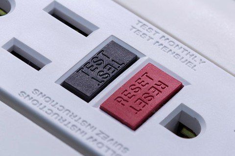
GFCI – “Ground Fault Circuit Interrupter.” A GFCI is an electrical safety device that automatically interrupts, or “opens” a circuit when it detects current imbalance between the supply and return sides of a circuit. When a GFCI trips and opens a circuit, it indicates that at least some of the electricity that went out to a load did not returning on its designated path. Maybe it went through a person’s body instead. GFCI protection can be delivered by either a special breaker to protect an entire branch circuit, or by a GFCI receptacle. Household GFCI receptacles are polarized and can usually be identified by their distinctive test and reset buttons. You should test GFCI’s monthly to ensure they are functioning properly.


https://www.youtube.com/channel/UCzEnpEZnLGtuVGyzpeT2Jpg

https://www.facebook.com/Electrician-ED-107527198489309

By David Sanders 15 Jun, 2022
The Complete Guide to Ground Faults and Ground-Fault Protection
By David Sanders 05 May, 2022
If you own an older home with Knob and Tube wiring or are considering an option to purchase one, you may have wondered how safe the wiring is and whether you should investigate options for getting it fixed. Then, if you’ve begun researching on your own, you could be running across conflicting information about Knob and Tube, both in costs and required treatment, and even in the relative safety of the system in general. How do you decide what to trust? Considering the importance of your peace of mind and the safety of your family, the following statement cannot be stressed enough: Nothing beats a qualified and licensed electrician’s in-depth assessment of your specific situation. This is especially vital with Knob and Tube wiring. The above warning being said, this article will help you make an informed initial assessment about your wiring by explaining the important things everyone should know about Knob and Tube. Knob and Tube, 101 Knob and Tube wiring was the first standardized wiring method used in the United States. It dates back to the late 1880s and early 1900s when homes were first built with installed wiring or were upgraded from the existing technology of the day for lighting and heat. Knob and Tube was the main wiring method used in homes until 1925 when other options became more affordable. Some homes built as late as 1940 were originally wired using the Knob and Tube method. Knob and Tube wiring looks just like its name implies. Two single-conductor cables, insulated with a natural rubber coating, are run in separate lines – one for hot, the other neutral – through a support system of ceramic knobs and tubes throughout the structure of the house. The two lines are generally kept about a foot apart, and installed in open spaces in attic rafters, floor and ceiling joists, and voids within walls. The knobs secure and support the wires so they maintain an air space between themselves and the surrounding wood framing. The tubes protect the insulation of the conductors from contacting surfaces when passing through them. The method also uses flexible sleeves to add further protection where conductors cross one another or pass by obstacles in their path. In many homes, electrical boxes were not used at all. Receptacles and light fixtures were fastened directly into wall finish and framing, with the knob and tube wiring feeding them from within ceiling and wall cavities. When splicing was necessary, installers twisted the bared ends securely, then soldered the joint, applied tar, and made several wraps with a cloth-backed adhesive tape for insulation. These splices could be made anywhere in the line and were not required to be put in accessible protective boxes like we do today. Knob and Tube, Pros and Cons One positive about existing Knob and Tube wiring is it usually looks very neat when unmodified. The pride and workmanship of the installers from that era is apparent. They liked keeping their lines straight in parallel rows and were careful to drive the nail cores of their porcelain knobs straight. This was open wiring they knew would be visible to anyone who looked, at least in spaces like attics and floor joists above basements. Also, the original installation method, with its sleeves, tubes, and knobs, was good at protecting the wiring. In its time, Knob and Tube was state of the art. Over the years, these installations have either weathered the test of time, standing as monuments to the past, or they’ve been replaced, improperly modified, or burned down. That leads to the present dilemma faced by homeowners and insurance companies. Is the wiring still safe, even if it has lasted until now? It can be difficult finding insurance for a Knob and Tube wired home. Many insurance companies will not offer a policy without a signed agreement to have the wiring replaced within 30 to 60 days. For those willing to ensure existing systems, there are usually further safeguards required , such as a certified inspection by a licensed electrician, assuring the wiring is safe and intact. The certification usually needs to be filed with the local building department. Physics is Against Knob and Tube Why would most insurance companies see Knob and Tube as too great a risk? Besides a poor track record, there are several problems with its design that has left it with a bad reputation. The first issue that jumps to most peoples’ minds is Knob and Tube is a non-grounded wiring method. By code, electricians can’t install modern three-prong receptacles without that third wire dedicated to equipment grounding, unless ground fault circuit interrupting devices are installed. So, while not having an equipment grounding conductor isn’t great, that really isn’t the main problem. The biggest issue Knob and Tube faces is a simple little thing called HEAT . All wiring must deal with heat in one way or another. Wiring usually must be installed in warmer areas, like attics, where ambient temperatures can range much higher than in the rest of the house. And wiring itself creates heat, as I’ll explain further on. But Knob and Tube especially falls short in this area for two main reasons: Inferior materials and electrical Physics. Inferior Materials Knob and Tube wiring has not aged well. Back in the day, manufacturers used a natural rubber coating to insulate conductors. Rubber, which oxidizes and cracks when exposed to heat, was used until plastics became more available and affordable, around 1925, and even then, the newer insulation still did not meet today’s standards. The aged insulation of Knob and Tube conductors often falls off in brittle chunks when touched. Insulation is very important for rating a conductor’s ampacity (capacity for carrying current without harming the insulation). For example, the original 1897 NEC standards rated the ampacity of a Rubber coated copper wire of 14-gauge at only 12 Amps. Compare that with our lowest rated building wire today, a 14-gauge copper wire with TW insulation, rated at 15 Amps. It would be a mistake to treat Knob and Tube wiring as if it will handle the same amount of current as today’s wiring, and yet the mistake is made continually. Electro-Physics, Just Another Fatal Problem for Knob and Tube Electricians are familiar with the crumbly nature of Knob and Tube insulation and know how challenging it can be to make it safe. But regardless of the material that was used, there’s an even greater problem in the way the wiring method was designed to be laid out. When electrical current passes through a conductor, two things happen. First, electrical current naturally generates heat from within a conductor at the atomic level. Since heat is cumulative, this adds up with the ambient temperature surrounding the conductors to cause more stress on its insulation. The hotter a conductor becomes, the worse it becomes at conducting electricity. So, heat, no matter where it comes from, is a bad deal for electrical wiring in general, but especially for any method with poor insulation to begin with. The second effect of electrical current through a conductor is the generation of an electromagnetic field around the conductor . This is an amazingly good principle that we harness in everyday applications such as transformers, motors, solenoids, and inductive heating. But the principle can play havoc with energy efficiency if our wiring is doing any of those things, unbidden, in places we do not wish. An uncanceled magnetic field causes every piece of ferro-magnetic metal (such as iron) within the influence of that field to begin heating up. In modern wiring methods, such as non-metallic cable (A.K.A., Romex®), the electromagnetic effect brilliantly cancels itself out by way of being a balanced circuit. Every circuit should have an equal amount of current going to and from a load, so one magnetic field is canceled by its opposing field in the conductor next to it. That is key: the two conductors must be within each other’s magnetic field. Qualified electricians know how important it is to balance the current in our cabling and other wiring methods, and we know how to do it well. But, not so with Knob and Tube! The entire design of keeping a circuit’s conductors separated so far apart in framing spaces makes electromagnetic balancing impossible. Each single conductor without its canceling partner nearby is forced to do much unnecessary work – magnetizing and heating every nail and staple it passes next to – in order to simply do its job of carrying current. One very likely scenario deserves mention here. Existing Knob and Tube, although never energy efficient, may still be safe if the entire wiring system has been left intact in its original form and hasn’t been moved around or modified. This includes not only the wiring but the original fuse sizing as well. However, over the years, most systems have been modified in one way or another. Although the NEC, since its first edition in 1897 , has required all new Knob and Tube installations to maintain spacing of at least an inch between its conductors and other surfaces, this hasn’t prevented later encroachments on the rule. It can be something as innocent as blown-in insulation surrounding the conductors. The required airspace is gone, the conductors with their rubber insulation have no way to dissipate heat. Sometimes other systems, such as ductwork and piping have been installed too close to open Knob and Tube conductors. This happens more often than anyone would guess, and it can be a deadly mix. Remember, the uncanceled electromagnetic field surrounding a single conductor will induce heat into a nearby metal pipe or duct. And if the conductor accidentally makes contact with one of these metal surfaces in one place, the rubber insulation can heat up enough to be burned completely off. In such situations, a duct or pipe would likely become energized. This could lead to electrical shock but may also cause sparking which could start fires if it sets off combustible materials. Knob and Tube Installers could not Foresee the Future In the early days of home wiring, electrical consumption was much lower than it is today. When Knob and Tube systems were being designed and installed, they could not have foreseen all the requirements we would ask of our electrical systems today. Most electrical utility services for Knob and Tube installations are limited to 60 Amps. By today’s rules, the minimum requirement for a service is 100 Amps, with many new installations opting for twice that much to provide for future expansion. Compounding the heat problem, Knob and Tube circuits are fewer in number than their modern counterparts. Having fewer circuits means modern users end up having to play musical receptacles with their appliances, plugging in elsewhere to allow one circuit a chance to cool off. Circuits tend to be overloaded often, which warms the tired insulation evermore. Modern Household Wiring Methods, Pros and Cons In the United States, most locales allow non-metallic cable (Romex®) to be used in wood-framed residences. NM cabling and other modern methods are superior to Knob and Tube both in material and design in the following ways: The most common conductors used in modern house wiring are insulated with thermoplastic (for example, THHN – a thermoplastic insulation with a nylon coating that can handle at least 30°C (86°F) more heat than [SB7] rubber). Thermoplastic lasts exponentially longer than natural rubber and can handle more heat over time. If it does begin to overheat, thermoplastic softens and melts but is less likely to burn. When cool again, it tends to shrink back into shape and retains its original flexibility. Overall, thermoplastic does its job well and protects individual conductors from leaking current, which allows conductors to be run together in the same cable or conduit. Better insulation means a conductor’s ampacity (capacity for carrying current without harming the insulation) can be rated higher. Compare a 14-gauge copper wire insulated with today’s THHN with the Rubber coated 14-gauge copper wire from 1897. Today’s version can handle 15 Amps easily and can even be rated as high as 25 Amps in the right conditions and application (say, for a motor circuit or HVAC) Non-metallic cable, like all other building-wire cables, carries an equipment grounding conductor. All modern household circuits are purposely grounded in compliance with the latest code standards. Modern manufactured cabling keeps all of a circuit’s conductors within the electromagnetic field of one another, allowing for correct balancing. This cancels unwanted induced-current into other nearby metals. More branch circuits are used which helps to spread load current across the wiring better, keeping it cooler. One drawback with modern NM wiring is it can be rather ugly. Installers often get in a hurry and do not make their runs look neat or orderly as with the old Knob and Tube method. This really depends on the installers, though. Wiring with modern cables can still be done neatly and smartly, with proper airspace maintained for cooling. Note: Neatness and longevity design should be selling points a good electrical contractor can use to showcase attentiveness to heat reduction and energy efficiency. You might ask to see pictures of their finished wiring projects. Watch out especially for too many cables bundled tightly together, a practice that would reduce air flow and prevent dissipation of heat. Options for Fixing Knob and Tube Issues At this point, most of us will agree, Knob and Tube is something better to face now rather than later. We’ve talked about reasons to have wiring professionally inspected. So, let’s discuss what choices a homeowner has for dealing with Knob and Tube wiring that has seen the end of its lifespan in terms of safety. Essentially, there are two options. You can do a complete removal and bring in all new wiring, or you can leave intact the parts of the Knob and Tube system that cannot be easily reached, while splicing to it with new branch circuits and wiring. The NEC allows for both approaches and is very particular about the guidelines for doing so. Local building codes and insurance companies may have more stringent demands. Ideally, it is usually best to remove Knob and Tube completely and rewire the entire house. This offers the best peace of mind if it can fit in your budget. If you decide to go this route, new wiring will be grounded. More branch circuits can be added as well to split up demand load over many circuits rather than the few originals. Everything will be brought up to code at the same time, with three-pronged, tamper-resistant receptacles, GFCI and AFCI protection throughout the home, and special required circuits attended to. A licensed electrician will be able to explain code minimums, in terms of number and placement of receptacles and other circuit needs. You may also want to upgrade your service and load centers. If you have existing fuse boxes, they can be replaced with updated breaker box load centers. Electricians can often fish new wiring to existing receptacle and lighting locations. They will add remodel boxes where needed and will remove old wiring wherever possible. Wherever possible, qualified electricians will try to remove all traces of the old Knob and Tube conductors once they’ve been cut out, but will always, at minimum, ensure that power cannot be tied back into them later by accident. Sometimes fishing wires will not be possible without cutting into the walls, usually at the tops or bottoms, and, if fire-blocking is encountered, above and below cross members in the middles of walls in order to run the new wiring through. The holes in the walls will need to be patched professionally and then refinished. Talk with your contractors beforehand to decide who will be responsible for these repairs. There are situations where it may make sense to allow some of the Knob and Tube wiring to remain. In spite of the age of some well-maintained homes, they remain attractive due to their period charm or exquisite and often irreplaceable finish work. For example, an electrician may be dealing with a full upgrade and, in coordination with the homeowner, may choose to leave a three-way switching circuit intact. The circuit may have been installed in a pristine wall from the second floor to the main floor around a beautiful staircase and may be impossible to fish with new wiring to the existing switch locations without cutting into the walls. You may have an historic home or simply one you feel needs special care. It’s okay to ask your electrical contractors about their plans for fishing new wiring without destroying your home in the process. If the option to remove only accessible portions of the wiring is made, electricians will pull new, grounded branch circuit wiring from the load center only to the last few inches of accessible Knob and Tube wiring for each existing circuit. New junction boxes will be mounted, and each Knob and Tube conductor will enter the box through its own bushed hole. The new branch circuit wiring will also be brought into the box through a separate hole, and splices will be made between the two systems. The electricians will need to take particular care with cracked wiring to keep its exposed insulation as intact as possible. They may use 600-volt rated tape or shrink tubing to accomplish this. If a metal box is used, it will be bonded with the grounding conductor, but the existing wiring that remains will not be connected to the grounding system and will remain ungrounded. Note: It is also important to realize that not all electrical contractors are specialized in dealing properly with Knob and Tube wiring, so if you plan to leave any portion intact, you will want to carefully discuss this with your electrician. Additional Considerations when Upgrading If you research online, you will find quite a range of projected costs for upgrading from Knob and Tube. Some sites suggest $4,000 to $8,000, while others suggest anywhere from $5,000 to $40,000. These conflicting projections are based on location and scale, but the differences might also simply be from having been posted at different periods in which costs changed dramatically. Labor costs will vary by locale, but with today’s material pricing, the lower ends mentioned elsewhere online of $4,000 would barely cover the materials for even the smallest of homes. But rest assured, though price ranges will vary, trustworthy contractors will have thorough discussions with you before pricing a project. They will know the right questions to ask to narrow down the needs of your specific situation, and then should offer up-front pricing options so you can be fully armed to make the best decision for yourself and your family. For efficiency, it is usually wise to combine as many upgrades at one time as possible. Consider not only upgrading the wiring, but the service and electrical panels as well. GFCI and AFCI protection is advised, as well as additional branch circuits to split up loading, and these can all be figured in and planned together with the rest of the work to make the entire project run as efficiently as possible. It is always best to make these decisions at the beginning and to stick to them, rather than adding random changes as the project progresses. Of course, each project will be different. Variables come into play, such as how accessible the circuits are, and the conditional methods a contractor is expected to use in maintaining existing finishes. Leaving parts of the existing Knob and Tube may cut down on costs a little, though the requirements for boxing and splicing do add up in labor time and materials. On the bright side, a good thing to remember is that replacing Knob and Tube wiring is in everyone’s best interest, including the lender on your mortgage. Look into options for financing an upgrade to new and safer wiring. Shop around. Sometimes your electrical contractor will even have a system in place to offer a payment plan and costs can be spread out over time. These plans often offer up to a six month grace period before accruing interest. Summary If you’ve made it this far in the article, congratulations! You are now armed with the important aspects of Knob and Tube you need to make informed decisions about your wiring. Key things to remember are: If you have concerns about your Knob and Tube wiring (or any other electrical issues), it is always best to get a qualified and licensed electrician’s in-depth inspection. Knob and Tube was a very difficult wiring method to maintain due to its design requirements for spacing and low tolerance for heat. Rubber coated copper does not have the same ampacity as today’s wiring and must not be treated as if it does. The NEC makes allowances for circuits that are not able to be removed during an upgrade. A qualified, licensed electrical contractor can give you the best appraisal of your existing system and best options and costs for upgrading. Consider combining upgrades to get the most efficient return on your investment. Ask your financial institution and electrical contractor about financing options. You should be able to spread the costs out over time. https://www.facebook.com/Electrician-ED-107527198489309
By info 21 Apr, 2022
By: David Sanders “Daaaaad! The breaker tripped in the basement again!” “Not again. That’s the third time this week!”
electrical hazards in the home
21 Jun, 2018
Homeowners want the assurance that their home is a safe and comfortable space to relax, work, play and make memories in. Learn how to keep your area safe and your loved ones protected.
Share by: